 The lights and AC outlets of my lab are controlled by low voltage relay system. I had used X-10 previously with marginal success. Commercial units were very expensive. I also envisioned using a panel of old
  bakelite knife switches for remote control to give it a steampunk flair to it. I did decide that the AC control board was going to use all through hole parts rather than surface mount. This makes rework easier if you don’t have the equipment to work with surface mount.
The 120 VAC is controlled by GE RR-7 Single Pole Single Throw (SPST) latching relays. These have two coils, one on and one off each energized by a short pulse of 24V AC. The relays are powered by a small 24V transformer and use the low voltage buttons for local control. I made a web based controller for remote control of the relays.
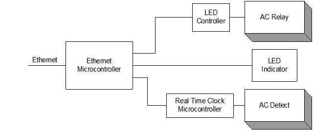
The idea is to send web based URLs with parameters to turn on and off the relays and return state of all the relays. The controller uses an Ethernet microcontroller (MCU) module that I call, “experiport”. It has a 10/100base-T through RJ45 Connector. The MCU interface of GPIO, SPI, I2C come to a pair of 22 pin connectors. This controls the LED controller for the opto-isolated zero crossing triac or AC relay, the LED indicator shift register and communicates with the SPI port of the real time clock and AC detect microcontroller. The LED controller, LED indicator and microcontroller interface to the Ethernet module using three independent bit-banged synchronous serial ports.
The Ethernet microcontroller sends serial data to turn on and off the LED in the AC relays, it turns on and off the LED indicator and communicates with the real time clock and AC detect microcontroller. The RR-7 relay doesn’t have a low voltage return contact to indicate state, so it must be detected by other means. The RR-9 does have a separate set of contacts to be used for state of the relay but couldn’t find any at a good price so had to engineer around the problem. It also requires additional wire conductors to bring it back to the control box.
Each coil on the relay has an opto-isolated zero-crossing triac AQH2213. These are called AC solid state relay. Zero-crossing means that the phototriac only conducts when the AC waveform is close to zero volts. This will reduce interference caused by the unintentional harmonic content of a truncated sine wave. It is opto-solated such when the LED illuminates, the phototriac will start to conduct. The relay is energized when either the local pushbutton is pressed or the AC relay is turned on. There is a bidirectional TVS (transient voltage suppression) diode on each winding to deal with flywheel effect of the relay inductor. A bell transformer supplies 24VAC to the board and has a standard slo blo fuse and a metal oxide varistor (MOV) for transient protection on the 24VAC lines.
The LED inside the AC relay is driven by the TI TLC5916IN LED controller. The TLC5916 is a serial to parallel shift register with current controlled outputs capable of directly driving eight LEDs. These can be daisy chained together to drive multiple of eight LEDs. The max current is set by a single external resistor and the current can be reduced in by programming the part.
Each relay coil has a LED portion of an opto isolated gate and series resistor across it so that the LED will light when the relay is energized. Another diode is used to rectify the power to the opto-isolated LED and prevent excessive reverse current on the LED. While the relay is energized, the opto isolated gate should output 8.33ms pulses.
The latching coils are in close enough proximity to each other that they start to behave as a transformer. That is, we will see a small AC voltage on the non-energize coil when the relay is energized. It will drive the AC detect opto isolated LED but not as strongly. The pulses I saw from the gate of the AC detector were much narrower than 8.33ms and are filtered out by the microcontroller.
The output of the opto isolated gate connect to a GPIO pin on an Atmel Atmega88. A transition on the pin wakes the part from sleep and it measures the period of each pulse. If the majority are close to 8.33ms wide, it sets the state of the relay in SRAM. This filters the non-energized coil pulses we might see. The MCU is battery backed up so it will keep the state of the relays even after power outage.. The MCU is an SPI slave to the ethernet board and can be queried for the relay state and time.
Software
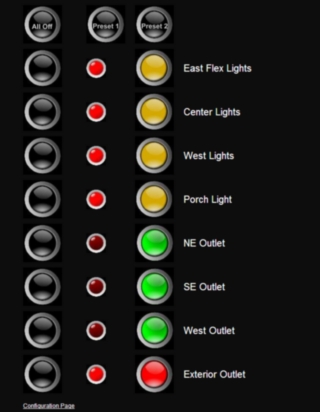
The experiport uses Adam Dunkel’s lwip stack on a Cortex M3 ARM microcontroller. One of the contribution is a http server (httpserver-raw) with server side includes. I tweak things a bit to borrow some ideas from RESTful interface but didn’t go into modifying the main server software although I did replace the filesystem with Chen’s fatfs. I also use javascript and AJAX techniques for my webpage. I have two pages: one which has on and off buttons with an indicator of the light state plus an “all off” and two preset buttons. A second page is for configuring the preset buttons, setting time, setting security, etc.
The web pages are on a SD card and I use Chen’s fatfs software to read the files from the server. So when the page is browsed, each button has a link that looks like:
<a href="javascript:void(0)" onclick="throwSwitch(2,'off')">
throwSwitch does some javascript which looks like:
function throwSwitch(pos, onoff) {
   var xmlhttp;
   var x, state;
   if (window.XMLHttpRequest) {// code for IE7+, Firefox, Chrome, Opera, Safari
       xmlhttp=new XMLHttpRequest();
    } else {// code for IE6, IE5
       xmlhttp=new ActiveXObject("Microsoft.XMLHTTP");
    }
    xmlhttp.onreadystatechange=function() {
       if (xmlhttp.readyState==4 && xmlhttp.status==200) {
          x=xmlhttp.responseXML.documentElement.getElementsByTagName("STATE");
          setLED(x[0].lastChild.nodeValue);
       }
    }
    xmlhttp.open("GET","relay?index=" + pos + "&state=" + onoff,true);
    xmlhttp.send();
}
This is the basic AJAX javascript. The experiport sees a get to relay with two parameters for which light switch and which state it should be. C code in the experiport parses the parameters and controls the specific relay. The response of the AC detector is now encoded into an XML reply including any light state, error state, fault condition, time to process, sending parameters, mother’s favorite color and all the other useless nonsense that usually accompanies XML.
The actual useful data from the XML of whether the light is on or off, is done in the AJAX onreadystatechange and is visuallized by calling setLED
function setLED(light) {
   document.getElementById("led1").src = (light & 1) ? onled.src : offled.src;
   document.getElementById("led2").src = (light & 2) ? onled.src : offled.src;
   document.getElementById("led3").src = (light & 4) ? onled.src : offled.src;
   document.getElementById("led4").src = (light & 8) ? onled.src : offled.src;
}
The XML is canned code which has server side includes. These are macros which get replaced with the tagged data when they are sent back to the client. It looks like
<?xml version="1.0" encoding="UTF-8"?>
<ACPORT>
 <STATE><!--#state--></STATE>
 <LEDFAULT><!--#ledfault--></LEDFAULT>
 <STATUS><!--#error--></STATUS>
</ACPORT>
The web page looks like this:

It works fairly well from the iPhone and I use that almost exclusively to control power.
This has been operational for about a year now and I’ve had to reset the experiport after hanging a few times. It is really great to be able to have the lights on as I walk to the lab at night.


